Customer may report that the vehicle is hard to fill with fuel or that the fuel pump nozzle shuts off repeatedly while trying to fill vehicle.
This customer complaint can occur due to a number of different causes. The fuel tank is the least likely cause of this condition. The following Diagnostic procedure can be used to diagnose the issues.
1. Is the vehicle a LX/LE/LC/L2?
a. Yes >> proceed to Step # 2
b. No >> proceed to Step # 4
2. Idle the vehicle 60 to 90 seconds upon stopping.
3. Does tank refill properly?
a. No >> proceed to Step # 4
b. Yes >> Inform the customer to idle the vehicle for 60 to 90 seconds upon stopping if vehicle was driven aggressively. This is due to the fact that on the LX/LE/LC/L2 the fuel tank is a unique saddle tank design and needs 30 to 60 seconds while the engine is running to level the fuel in both half's of the fuel tank. Allowing the vehicle to idle for this amount of time will let the fuel pump transfer fuel to the left side tank, opening the control valve and allowing normal fuel filling.
4. Disconnect the vapor recirculation tube at the fuel tank.
5. Attempt to refill fuel tank.
6. Does tank refill properly?
a. Yes >> Proceed to Step # 7
b. No >> Proceed to Step # 11.
7. Reconnect the vapor recirculation tube at the fuel tank.
8. Disconnect the other end of the vapor recirculation tube at the fuel filler tube.
9. Attempt to refill fuel tank.
10. Does tank refill properly?
a. Yes >> Replace fuel filler tube.
b. No >> Replace the vapor recirculation tube.
11. Disconnect the control valve to EVAP canister tube at the fuel tank.
12. Reconnect the vapor recirculation tube at the fuel tank.
13. Does tank refill properly?
a. No >> Replace Fuel Tank.
b. Yes >> Proceed to
14. Reconnect the control valve to EVAP canister tube at the fuel tank.
15. Disconnect the control valve to EVAP canister tube at the EVAP canister.
16. Attempt to refill fuel tank.
17. Does tank refill properly?
a. Yes >> Blockage is in the EVAP Canister, or ESIM, or Clean air hose (ESIM vent hose), or filter. Diagnose appropriately.
b. No >> Replace the control valve to EVAP canister tube.
To comprehend what is going on here requires an understanding of components in both the fuel system and the emissions control system. I waded through quite a bit of data online to get a superficial understanding---here are some of the pieces of information I found:
-----------------------------
Evap
The EVAP emissions system is designed to contain gasoline fumes from the gas tank the vent them to the intake manifold for combustion.
The carbon canister is the central part of the system. It is located behind the circular cover under the rear of the vehicle. It is connected to the gas tank vent lines, N80 purge valve and the leak detection pump. Gas tank vapors flow through the vent lines to the carbon canister where the are contained by the charcoal. The vapors are purged into the intake tract through the ECU controlled N80 valve during engine operation. The leak detection pump pressurizes the system to determine if there are any faults that could cause a vacuum leak on the intake system.
Why?
EVAPORATIVE CONTROLS
Gasoline evaporates quite easily. In the past, these evaporative emissions were vented into the atmosphere. 20% of all HC emissions from the automobile are from the gas tank. In 1970 legislation was passed, prohibiting venting of gas tank fumes into the atmosphere. An evaporative control system was developed to eliminate this source of pollution. The function of the fuel evaporative control system is to trap and store evaporative emissions from the gas tank and carburetor. A charcoal canister is used to trap the fuel vapors. The fuel vapors adhere to the charcoal, until the engine is started, and engine vacuum can be used to draw the vapors into the engine, so that they can be burned along with the fuel/air mixture. This system requires the use of a sealed gas tank filler cap. This cap is so important to the operation of the system, that a test of the cap is now being integrated into many state emission inspection programs. Pre-1970 cars released fuel vapors into the atmosphere through the use of a vented gas cap. Today with the use of sealed caps, redesigned gas tanks are used. The tank has to have the space for the vapors to collect so that they can then be vented to the charcoal canister. A purge valve is used to control the vapor flow into the engine. The purge valve is operated by engine vacuum. One common problem with this system is that the purge valve goes bad and engine vacuum draws fuel directly into the intake system. This enriches the fuel mixture and will foul the spark plugs. Most charcoal canisters have a filter that should be replaced periodically. This system should be checked when fuel mileage drops.
History lesson
The need to control the emissions from automobiles gave rise to the computerization of the automobile. Hydrocarbons, carbon monoxide and oxides of nitrogen are created during the combustion process and are emitted into the atmosphere from the tail pipe. There are also hydrocarbons emitted as a result of vaporization of gasoline and from the crankcase of the automobile. The clean air act of 1977 set limits as to the amount of each of these pollutants that could be emitted from an automobile. The manufacturers answer was the addition of certain pollution control devices and the creation of a self adjusting engine. 1981 saw the first of these self adjusting engines. They were called feedback fuel control systems. An oxygen sensor was installed in the exhaust system and would measure the fuel content of the exhaust stream. It then would send a signal to a microprocessor, which would analyze the reading and operate a fuel mixture or air mixture device to create the proper air/fuel ratio. As computer systems progressed, they were able to adjust ignition spark timing as well as operate the other emission controls that were installed on the vehicle. The computer is also capable of monitoring and diagnosing itself. If a fault is seen, the computer will alert the vehicle operator by illuminating a malfunction indicator lamp. The computer will at the same time record the fault in it's memory, so that a technician can at a later date retrieve that fault in the form of a code which will help them determine the proper repair. Some of the more popular emission control devices installed on the automobile are: EGR VALVE, CATALYTIC CONVERTER, AIR PUMP, PCV VALVE, CHARCOAL CANISTER.
Refueling and ESIM
During refueling, pressure is built up in the evaporative system. When pressure approximately .5 inches of water, the large
check valve unseats and pressure vents to the fresh air filter.
Conversely, when the system cools and the resulting vacuum lifts the small check valve from its seat and allows fresh air to
enter the system and relieve the vacuum condition. When a calibrated amount of vacuum is achieved in the evaporative
system, the diaphragm is pulled inward, pushing on the spring and closing the contacts.
The ESIM conducts test on the evaporative system as follows: An engine off, non-intrusive test for small leaks and an engine
running, intrusive test for medium/large leaks.
The ESIM weights seal the evap. system during engine off conditions. If the evap. system is sealed, it will be pulled into a
vacuum, either due to the cool down from operating temperature or diurnal ambient temperature cycling. When the vacuum
in the system exceeds about 1” H20, the vacuum switch closes. The switch closure sends a signal to the NGC. In order to
pass the non-intrusive small leak test, the ESIM switch must close within a calculated amount of time and within a specified
amount of key-off events.
If the ESIM switch does not close as specified, the test is considered inconclusive and the intrusive engine running test will
be run during the next key-on cycle. This intrusive test will run on the next cold engine running condition.
Vapor recirculation tubes
Fuel vapor recirculation tubes are employed in motor vehicle fuel tank filler tubes in order to provide vapor recirculation during refueling from a nozzle inserted in the filler tube with a mechanical seal provided about the nozzle. The recirculated vapor provides a make-up flow below the nozzle seal to prevent the flow discharging from the nozzle from creating a vacuum in the filler tube and prematurely activating the automatic nozzle shutoff.
Fuel Tank
This vehicle uses a saddle type tank, a reservoir on both sides of the rear drive shaft. The fuel pump is in the module on the left side of the vehicle and the fuel pressure regulator is in the module on the right side of vehicle. The fuel outlet is on the right side and supplies fuel to the engine. The fitting on the fuel pump module (left side) is a vapor line fitting that connects to the right side module. Both modules have fuel level sending cards. There are 2 hoses that connect the modules together, one is the fuel supply line the other is a return or siphon hose. The lines are removed from the fuel pump module when servicing either unit. The ORVR (Onboard Refueling Vapor Recovery) control valve is in the right side module.

The passenger side fuel tank module is the one on the left, the drivers side module containing the fuel pump is on the right.
Fuel Pump
The way the pump works is as follows, fuel enters the reservoir of the driver side module. The fuel pump pumps the fuel through the filter to the passenger side module through a supply line inside tank. The pressure regulator inside the passenger side module regulates the pressure at 58 psi . All unused fuel that is not sent to the engine is fed through a venturi at the bottom of the passenger side module. This creates a low pressure siphoning effect and draws fuel from the passenger side of the tank and transfers it to the drivers side tank via siphon hose inside the tank. While the vehicle is running the fuel in the passenger side of tank is continuously transferred to the drivers side. Fuel will continue to fill the drivers side tank till it reaches the bridge section and then start to spill over to the passenger side.
As stated above we have two fuel level senders, the reading of these senders are averaged out to give us the fuel gauge reading. When we are diagnosing a sender concern the passenger side reading should never be higher than the Drivers side reading. It is possible, depending on fuel level and driving habit before diagnosing, to spill fuel over to the passenger side that might indeed show a lower resistance value than the driver side.
The tech needs to order the correct part when replacing, the senders, modules, and tank as all are able to be replaced individually.
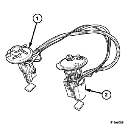
(1) Passenger side fuel tank module. (2) Driver side fuel tank module. Driver side pumps fuel to the passenger side module, and from there to the fuel line. Passenger side reservoir siphons gas to the driver side reservoir, and sending unit cards in each module average the fuel level in the tank.
---------------------------
In the end, I did some sleuthing, took a few snapshots, and drew up this hideous diagram.

The diagnosis section of the bulletin describes first testing whether the (1) vapor recirculation tube or (2) fuel filler tube are the problem. If these are okay then it's likely something internal to the gas tank or emission control system. First check EVAP line at fuel tank (3) and then at EVAP canister to determine if it's the gas tank, EVAP line, or beyond.

The vapor recirculation tube protrudes from the fuel tank reservoir on the passenger side to connect to the fuel filler tube.

To get to the fuel filler tube you need to remove the left rear tire and splash shield.
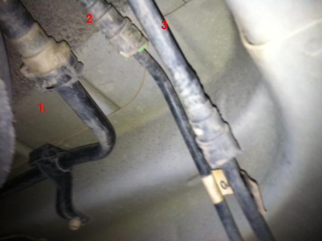
The (1) EVAP, (2) Fuel, (3) and Purge Solenoid lines protruding from passenger side fuel reservoir.

(1) Evap Canister, (2) ESIM (Evaporative Systems Integrity Monitor valve), (3) Filter. The line extends up to the front of the vehicle, and the ending stump can be seen if you peer under the hood past the engine block and transmission, behind the ABS module, as below:


On the passenger side of the the engine block, you'll see the (1) fuel line and (2) purge solenoid line coming from the fuel tank.

The (1) fuel line then feeds into the (2) fuel rail.

The other line feeds into the Purge Solenoid, and continues from there to the intake manifold.
1 comment:
it really interest me to read a lot in your post. . thanks for sharing it to me. .. I have now idea on my dissertation .vapor recovery unit
Post a Comment